
In this workshop we will build and program a humidity and temperature sensor ourselves with Tasmota. Then we will do this with a distance sensor.
Erik Roukens
 |
|||
Member benefitsThe self-build kit in this workshop can be ordered with a discount as an HCC member. Click here for more information |
Getting started with electronics and programming yourself is one of the most fun things to do. In this workshop we will build and program a humidity and temperature sensor with Tasmota, followed by a distance sensor. In the coming issues we will continue on this and we will also get started with Home Assistant, among other things.
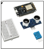
For this workshop you need a breadboardjumper wires, ESP8266 and DHT11 sensor (DHT11). We have collected these in a self-build kit that you can easily order and with a discount at tinytronics.nl, at least if you are an HCC member. Look for this in the box Self-build kit. In addition, we use the free software Tasmota in this workshop.
First the different parts are explained, then we get started.
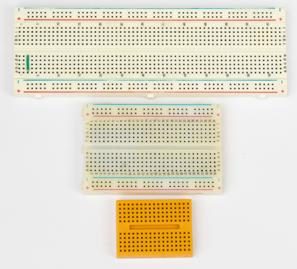
Breadboard
The name breadboard comes from the fact that in the past a wooden breadboard was used to screw components on. The name has remained, but the wood has now been replaced by a plastic edge with fixed metal power distribution on the inside.
How do breadboards work?
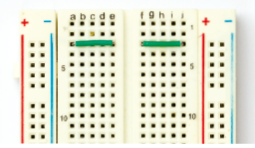
Points a, b, c, d & e (and on the other side f, g, h, i & j) are internally connected per row. There are 60 rows on the large model and 30 rows on two sides on a small model. On the right and left sides there is a red (+) and blue (-) line from top to bottom. This line indicates that the holes on these tracks are connected
The left can be used as 3.3 volts and the right as 5.0 volts. The contact points are exactly 2.54 mm apart. Most components you can buy, such as the ESP826, use this sizing. If you want to see in great detail how the edges fit together, take a look at this Elecrow page: www.elecrow.com/blog/how-to-use-a-breadboard-for-beginners.html
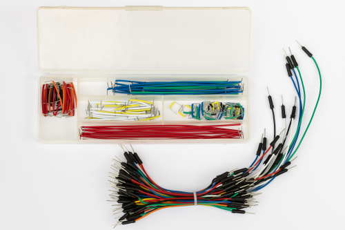 Jumper wires
These wires allow you to quickly connect two components. The pins fit perfectly into the holes on the breadboard. In the box you see hard wires, the bundle underneath are flexible wires. In the workshop we will use the flexible wires.
ESP8266
This is the unit that we will connect everything to and where our program will run. The ESP8266 comes in many different sizes and shapes, here are a few examples. For this workshop we will use the largest size (left), the second model is called WEMOS and the one on the far right is called ESP-01. The smaller models have fewer connection options, but are often more practical for most projects.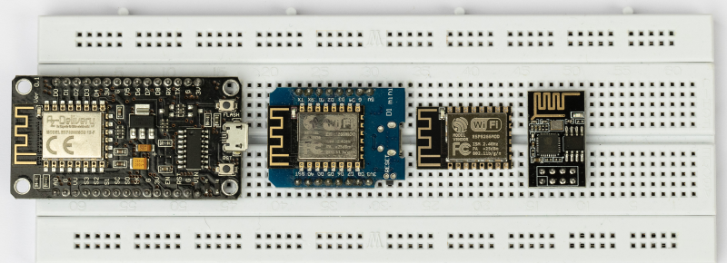 Below is an overview of the connection pins (GPIO) of the ESP8266 in this workshop. You can power the ESP8266 via the USB port, but you can also directly supply 5 volts to Wine PIN. Internally, the board converts 5 Volts into 3.3 Volts. The Input/Output pins of an ESP8266 can only handle 3.3 Volts. The unit will not survive higher voltages, so be careful if you also use 5 Volts in your project. Via one of the GPIO pins (General Purpose Input Output) we will soon connect the sensor.
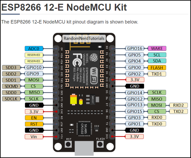
 |
|
Source https://randomnerdtutorials.com/esp8266-pinout-reference-gpios/ |
More infoMore info about |
||
Tasmota
Tasmota is free software, written by the Dutchman Theo Arends. Once Tasmota is installed, it basically runs completely locally. It can then communicate within your network with Home Assistant and other programs such as Node Red. Communication with Tasmota can run via the Serial port, MQTT, HTTP or WEB UI.
To communicate with Home Assistant, we will need MQTT at a later stage.
ESPEasy is an alternative to Tasmota, it can also communicate with Home Assistant and offers some other possibilities. For this workshop we will limit ourselves to Tasmota.
Sensor DHT11
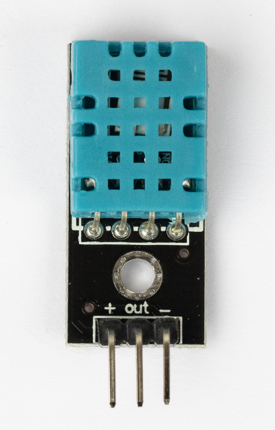 The DHT11 sensor is a simple, low cost Digital temperature and humidity sensor. It uses a capacitive humidity sensor and a thermistor to measure the surrounding air. It puts a digital signal on one of the data pins (GPIO). The sensor will give new data once every 2 seconds.
We will soon connect the leftmost pin with the (+) sign to 3.3 Volts. The middle pin (OUT) goes to one of the GPIO inputs of the ESP8266. We will soon connect the (-) to a GND (Ground or Ground) pin of the ESP8266.
Be careful with this: if you use the plus and min turns over, the sensor will become very hot and burn out!
If multiple sensors need to be connected, for example an indoor and outdoor temperature sensor, each (OUT) of a sensor must be connected to a new pin of the ESP8266. Each sensor therefore needs its own data pin.
Note: there is also a DHT11 that is delivered without mounting board, this one has 4 pins. To make this model work properly, we need a 4.7 Kilo Ohm resistor that we have to connect between the DATA and VCC pin.
Wiring
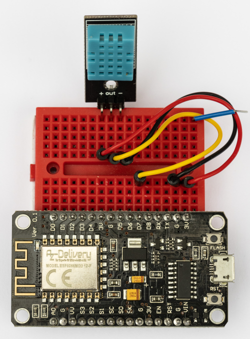
The DHT11 can handle a voltage of 3.3 to 5 Volts. There are several 3.3Volt connections on both sides of the ESP8266. It doesn’t matter which one you take. The pins we need, namely 3V3 (3.3Volt), GND and pin D7 are all located on one side of the ESP8266. Now plug the ESP8266 into the breadboard as shown in the image below.
 Please note in the next step: if you plus and min If you turn it around, the sensor will become very hot and burn out!
The colors of the wires are not important, but can make it easier. In the picture you see:
- Red goes from the 3.3 volts (3V) of the ESP8266 to the (+) of the sensor
- Yellow for data goes from the ESP8266 pin D7 to the (out) of the sensor
- Black for Ground (G) to the (-) of the sensor.
Note: the blue wire in the photo is only used to bend the red, yellow and black wires away for the photo. It has no other function.
Tasmota
To get everything working, we need to load the ESP8266 with the free software Tasmota. We do this by connecting the ESP8266 to the computer with a micro USB cable. Programming is very easy via a web page with a Web Installer: https://tasmota.github.io/install/ On this page we can choose a version of Tasmota. 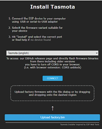 The pre-selected version (Tasmota English) is good for this demo, but you can also choose the Tasmota NL version if you want everything in Dutch.
In this workshop we will use the English version. Tasmota can do a lot and that is why specific versions of Tasmota have been created; other versions of Tasmota are specifically for Displays, Infrared, Zigbee, KNX etc.
It is even possible a custom-version of Tasmota that has exactly everything you need. If you make/have such a version, you can find it on the Webpage in the dotted box drop and programming. Setting up a special version yourself is something for a later workshop.
Connect and install
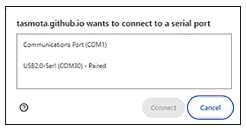 Once the ESP8266 is connected via USB cable, click the Connect-button. The serial-port image should now appear (opposite).
If you don’t know which COM port it is, unplug the ESP8266 when the Serial-Port Window is open. You will then see the gate disappear. When you plug the plug back in, you will see the port return. If you get error messages in this section about a serial port erroris the driver needed to control the CH340 chip on the ESP8266 is probably not installed. https://learn.sparkfun.com/tutorials/how-to-install-ch340-drivers/all explains how to install them. Select the correct one COMgate and click on Connect.
 In the next window click on Install Tasmota (English). Then check the box Erase devicebecause we want all old data and wifi data to be gone before we reprogram the unit. Then confirm by clicking Install to click.
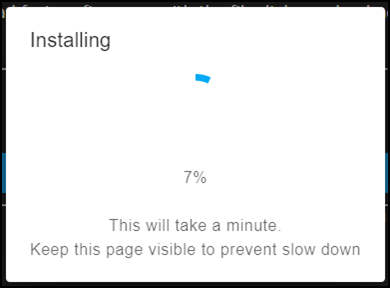
Programming is complete after approximately 1 minute:
 Then click on Next and select the correct WiFi Access Point and enter it WiFi Password in. Finally, click Visit Device to go to the unit’s web page.
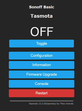
If everything went well, you should now see the Tasmota welcome page. Click on it Configuration:
Now click Configure Module. Tasmota is set by default for a Sonoff Basic with limited options:
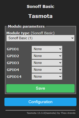 Click in the top bar and select the last option in the long list of possibilities (Generic (18)). Then click on Save and wait about 30 seconds. You get the standard Tasmota home menu again; click again Configuration and then click again Configuration Module to get to this same menu with the GPIO configuration.
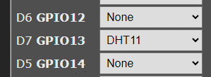
 If all went well, you should now see a longer list of GPIO points. Find D7 GPIO13 in the list and select there DHT11 in the menu.
You should now see this:
 click on Save and wait 30 seconds. If everything is connected properly and Tasmota is programmed correctly, the data from the sensor will be visible on the front page of Tasmota. The DHT11 measures temperature and humidity. It Dew point is a calculation between temperature and humidity.
Other sensors
There are other sensors to experiment with, such as the AM312 (infrared motion detector), BME280 (slightly better temperature sensor with humidity and barometer), BH1750 (light sensor) and APDS-9960 (hand gesture sensor).
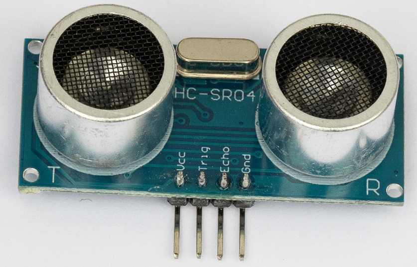
Here we will discuss the HC-SR04, a sensor that measures distance in centimeters. We can make it work in parallel with the DHT11. For this we need a different version of Tasmota, namely the version that specializes in sensors. In a few steps we can achieve this.
 Go back to https://tasmota.github.io/install/ to install Tasmota.
Now select the Tasmota Sensors-version, install it on the ESP8266 and set up the WiFi again. Visit the unit’s web page and set up via Configuration and Configure Module the unit on Generic (18) in.
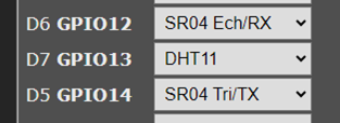
Then via Configuration and Configure Module
Set up GPIO 12, 13 and 14 as shown here:
The new sensor now needs to be wired onto the breadboard: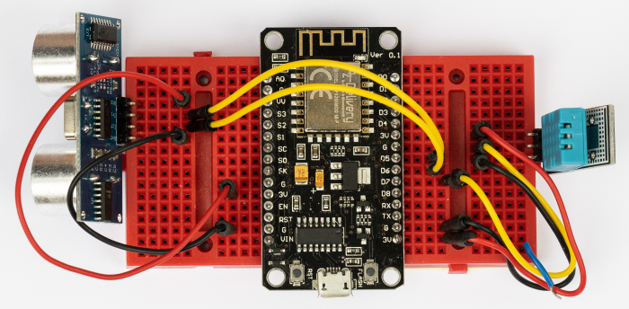
“3V” (3.3 volts) to the
“Vcc” of the sensor
“D5” (GPIO14) to
“Trig” of the sensor
“D6” (GPIO12) to
“Echo” of the sensor
“GND” Unpleasant
“GND” of the sensor
If you did everything correctly, you should now be able to see the distance on the Tasmota front page along with the DHT11 information we already had: