Do you remember the time when you played arcade games in arcades or at the local snack bar? With a Raspberry Pi we can affordably bring that nostalgia back to life.
Wim Dewijngaert
The golden years of the coin-up arcades are long gone, but many people in their 40s and 50s no doubt still fondly remember the days when their pocket money was devoured by the popular games machines. The graphics on the home computers of that time paled in comparison to the graphic violence in the arcades. So the game fans spent their free time in an often musty, dark hall, with the beeping sounds of Pac-Man and Donkey Kong as the soundtrack of their childhood.
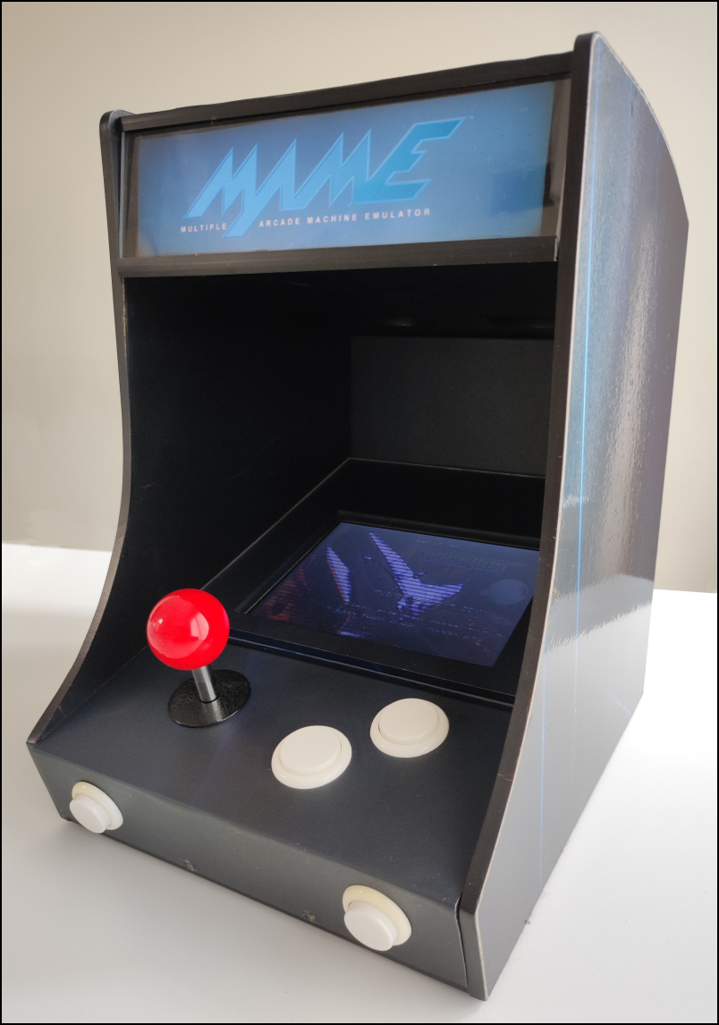 |
| This is what our mini-MAME machine looks like |
Nostalgia
Can we bring some of that nostalgia back to life? Naturally. Nowadays you can buy an arcade cabinet for a few thousand euros, which often runs the MAME emulator. This software has been available since 1997 and will catapult you back to the eighties. For many years the driving force behind this feat was the Italian Nicola Salmoria, who wrote the emulator as a thesis during his studies. Of course, for such a large game cabinet you have to have some space in the house, and that’s where the shoe often pinches. Can it be made smaller, in mini format, with, for example, a Raspberry Pi? The MAME emulator can be compiled on almost all platforms, including the latter. A ready-to-use download has been available with the frontend RetroPie ingrained. But MAME doesn’t run flawlessly on it, and even a recent Pi 4 has a hard time supplying enough computing power.
Benoit, a young man from Quebec, decided to do something about this and took control of the Raspberry Pi OS Lite operating system. He stripped out all unnecessary components – including the entire graphical interface – and added the front-end software Attract Fashion up. A lot of games now run smoothly on a Pi 4 or Pi 400 with only 1 GB of memory. You can read (in French) exactly how he managed that and what steps you need to follow to try it out on his Github page: https://gist.github.com/sonicprod. With some skill we craft a nice box around it ourselves, and our own mini version is born.
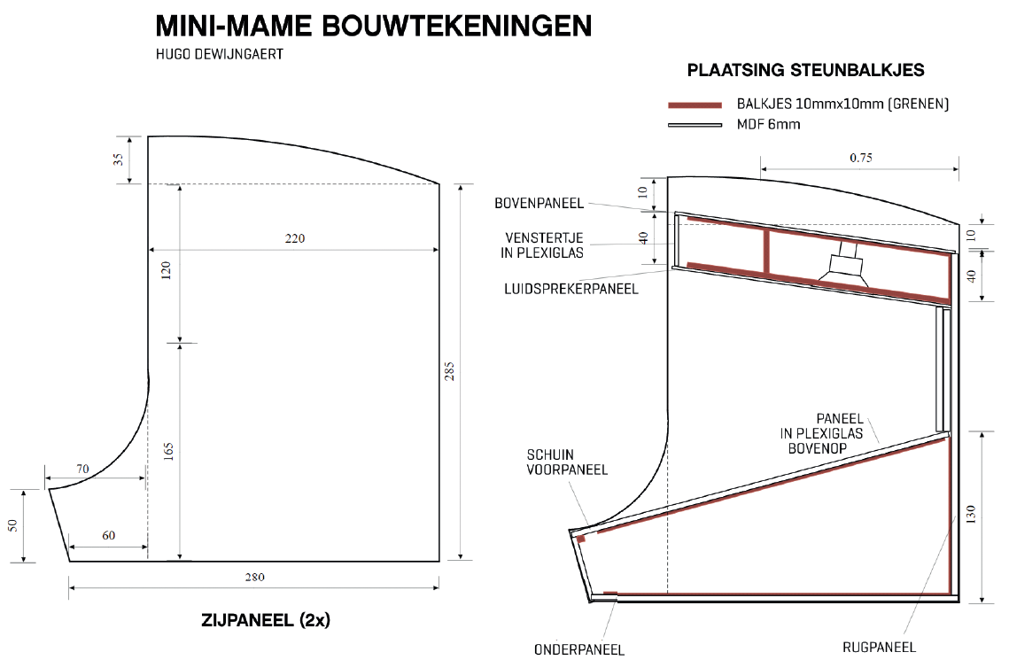 |
| An excerpt from the construction drawing, which you can download on our site |
Grocery listThese are the parts we used in our design, along with an order link on Amazon. Perhaps you still have some material in your closet, or the parts can be found cheaper elsewhere, such as on Aliexpress.
|
To work
Via a Google Drive link, which can be found at http://forum.arcadecontrols.com/index.php/topic,162889.0.html, we first download an image file preconfigured by Benoit. We unpack this with 7-Zip (http://www.7-zip.org). The final IMG file can most easily be ‘baked’ on an SD card (of at least 12 GB) with Win32 Disk Imager (https://win32diskimager.org).
After writing, we add the file via the Windows explorer in the root directory on the SD card wpa_supplicant.conf up with this information:country=NLctrl_interface=DIR=/var/run/wpa_supplicant GROUP=netdevupdate_config=1network={ssid="WIFI_SSID"scan_ssid=1psk="WIFI_PASSWORD"key_mgmt=WPA-PSK}
Of course, replace the name of your WiFi network and the password. To further configure the Raspi, we temporarily connect it to a USB power supply and set up a wireless connection via our PC. This is easiest with WinSCP (https://winscp.net), which contains both an SFTP and a PuTTY terminal. We will need both soon.
Make a new connection in WinSCP to the IP address of the Raspi (with the application Fing you can easily find this on your mobile phone). Use ‘pi’ as username and ‘raspberry’ as password. Then choose ‘open in Putty’ in the menu and type the password again.
We will now first make the data partition on the SD card larger and activate the Attract Mode frontend. Tap:rw./expand-data-partition.shfrontend attract
Then run the command sudo raspi-config off and make sure that at System/Audio the audio output goes to the headphone jack.
Then you tap sudo nano /boot/config.txt. Change disable_overscan to 0, remove the # for the four lines starting with ‘overscan’ and also remove the # for the parameters ‘over_voltage’ and ‘arm_freq’.
In principle we should Attract Fashion were going to provide a list of games, logos, screenshots and videos themselves, but someone has already done this tricky job for us and puzzled together artwork for just over 500 games. Open the same page where you found Benoit’s image and look for post number 317. There you can download the file download attract.7ztogether with MAME_pi_art.zip (via a Google Drive link). Of 7-zip extract your both files to a temporary directory on your PC.
Through WinSCP delete the contents of /data/attract on the Raspi and then copy the files from the file attract.7z here. Then you copy the directories flyer, marquee, snap and wheel from MAME_pi_art.zip to /data/attract/scraper/MAME.
In the file romnames.txt that you can find in the message on the forum, all the names of the ROMS of the games you need. You can download the ROMS from https://www.retroroms.info/page/bda, but please note: due to copyright you must in principle have the original arcade cabinet. All ZIP files should be copied to /data/mame/roms.
Finally, we type in Putty:arcademodesudo shutdown
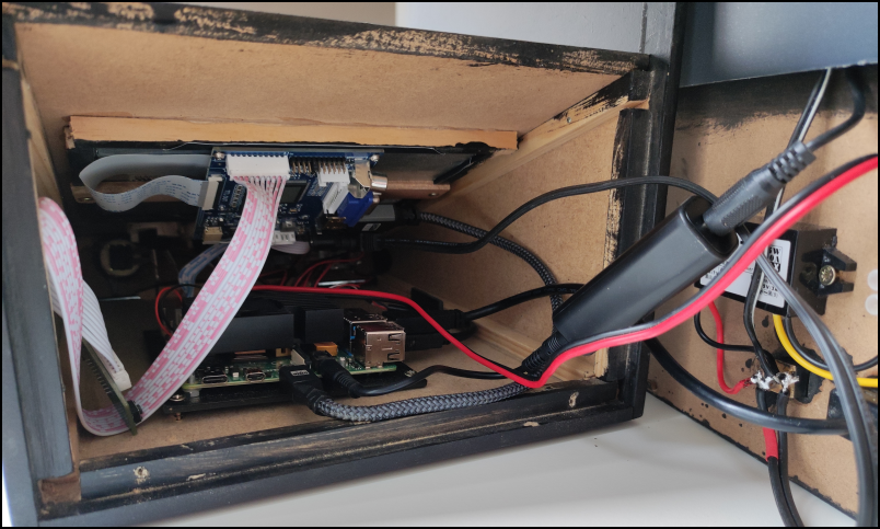 |
| Crafts along the back |
Housing
Now it’s time to assemble the housing. Attention: some basic knowledge of woodworking and electronics is a must for this. If a saw and soldering iron are part of your standard equipment, then our measurement plan that you can find online will help you a lot on your way, although you are of course free to add some creativity. You start by sawing out the different panels according to the construction drawing. The left and right panels are mirror images of each other. Then place the wooden support beams (10mm by 10mm) on both side panels. Use wood glue for this. Take your time to let it dry completely. Then prepare the speaker panel. The LED lighting will later be placed on the vertical plate at the front and the audio amplifier at the back. Note the hole (3mm) through which the power wires of the LED lighting will have to pass. You also glue the bottom plate.
Finally, glue the four panels (left, right, bottom plate and the speaker panel) together to form a stable box. Let everything harden well. Now finish the sloping front panel. Drill the holes and saw the opening for the display. We glue four bars of 10mm x 10mm around the inside of this opening. Pay close attention, because the display is not symmetrical in its housing. There is an elevation in the rear wall through which the wires of the 12V power supply (for the amplifier and the LED strip) and the audio cable run. It is best to finish the housing neatly using a lot of filler, sanding, priming and varnishing. We have chosen black lacquer to give the cabinet a sleek and high-gloss appearance. Good preparation is half the work: the neater you putty and sand, the less you need to paint. After the first layer of primer, you can sand again neatly with grit 150 and the finishing can begin. We have chosen to finish the whole with a self-designed sticker sheet. The sides of the side panels are finished with black ironing tape. Finally, you can put a 205mm x 200mm plexiglass on top of the screen to give it some protection.
Connections
A connection diagram can also be seen on the construction drawing. The 12V from the external power supply goes to a male plug on the back of the cabinet. That way we can easily disconnect and store the power supply later. Inside we split the power supply line in two: a cable goes to the top of the machine to connect the LED strip (for lighting the marquee) and power the amplifier, another cable goes to the bottom and serves as a power supply for the screen and the inverter. The inverter converts the 12V into 5V, which we finally use as a power supply for the Raspberry (on pins 4 and 6). Use a good quality cable with a diameter of 0.75 mm.
You need to trim the LED strip to illuminate the marquee to the desired width. If you find the lighting too bright, you can optionally add a 100 ohm resistor. We printed the marquee itself on transparent paper with an inkjet printer and it is behind a plexiglass.
You connect the two speakers to the amplifier. You mount the USB extension cable on the back of the box and connect it to one of the USB ports on the Raspi. That way you can connect a keyboard without having to open the box. The fan kit to keep the Raspi cool is easy to install with the included instructions. You plug the audio cable into the headphone output, then go through the loop noise isolator and ends at the amplifier. The HDMI cable goes from the Raspi to the screen. You connect the buttons and the joystick to the encoder, which you plug into a USB port of the Raspi. At the front of the box there will be two smaller 24mm buttons that serve to insert a coin and exit a game, above that on the left we will mount the joystick and on the right two 30mm push buttons.
The screen comes with a number of printed circuit boards, which you have to connect to each other. We also refer you to the supplied manual for this. We leave the buttons to operate the menu of the display loose in the housing and are in principle no longer necessary once everything has been adjusted. By default, the brightness is a bit too weak, so you probably have to adjust this.
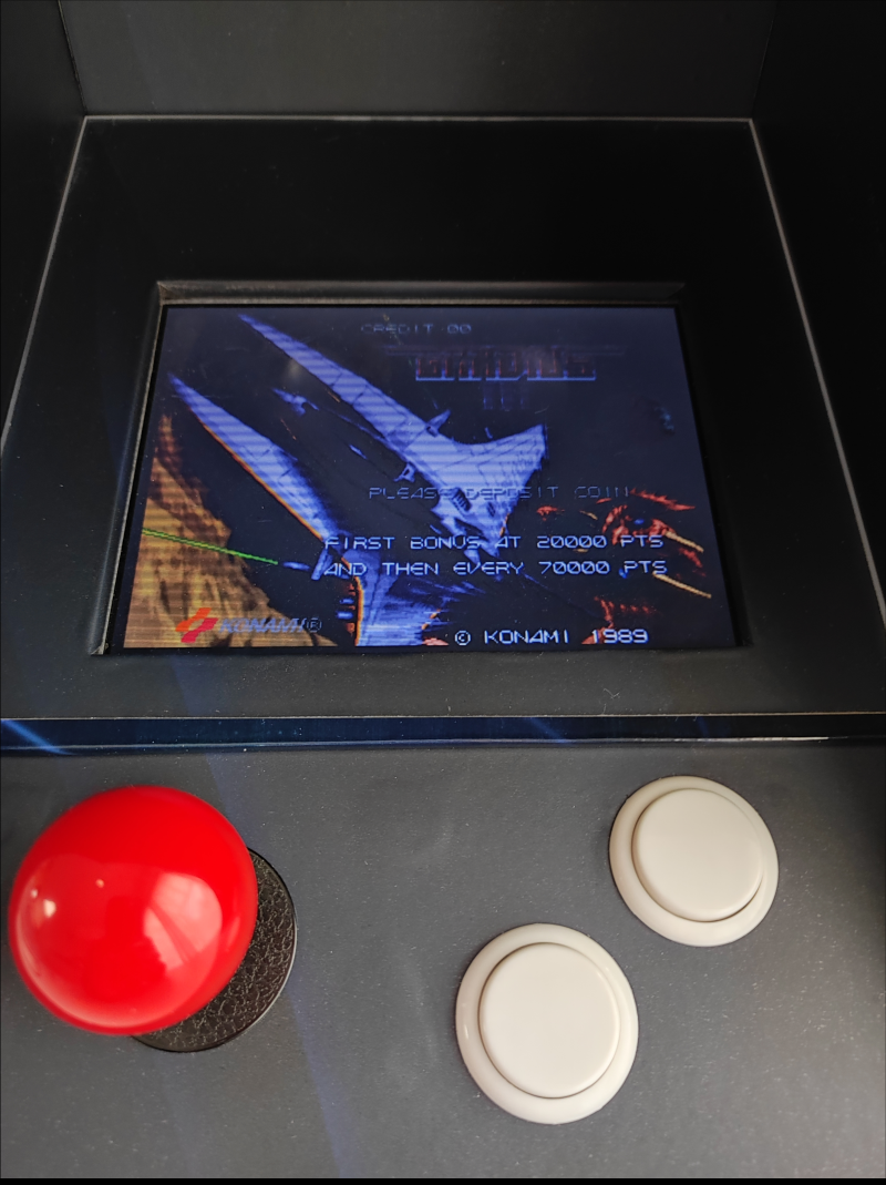 |
| A look at the screen |
Configuration
Finally, we still have to configure the buttons and the joystick. To do this, connect an external USB keyboard to the back and plug the power supply into the socket. If all goes well, you will first see the MAME logo and a few seconds later the graphical interface of Attract Mode. Now press the tab key and then go to ‘Controls’ in the menu to configure the joystick and buttons.
Then start a game. Once the MAME emulator is open, press again tab to set the joystick and the four buttons. With the left button in the front we throw in a coin. The right button becomes the escape button. We define the other two buttons as Player 1 Start/Button 1 and Player 2 Start/Button 2. Once that task is completed, the closet is ready!